
What is a Sensor? How an IR and Ultrasonic Sensor Works? Different types of Sensors

Sensor
is a device that detects and responds to some type of input from the physical
environment and also it converts any physical quantity to its equivalent
electrical signal. There are different types of sensor are available, there is
a Temperature sensor, Light sensor, Voltage Sensor, Smoke Sensor, Gas sensor,
Fire sensor, Magnetic Sensor, etc.
A
sensor can also receives and responds to a signal or stimulus. Here, the term
"stimulus" refers to a property or a quantity that needs to be converted
into electrical form. The output of the sensor is generally a signal that is
converted to human-readable display transmitted electronically over a network
for reading or further processing.
A transducer is differ
from Sensor in the way that a transducer converts one form of energy into other
form whereas a sensor converts the received signal into electrical form only.
IR wireless sensor is a
wireless technology in devices or systems that convey data through infrared
(IR) radiation. Infrared is a type of
radiant energy that's invisible to human eyes and electromagnetic energy at a
wavelength or wavelengths somewhat longer than those of red light. In the shortest-wavelength IR borders visible
red in the spectrum and at longest-wavelength IR borders radio waves.
ORIGIN
OF NAME:
The name Infrared means
"Below Red", the Latin word "Infra" means
"Below". Red is the color with the longest wavelengths of visible
light and Infrared light has a longer wavelength (and so a lower frequency) than
that of red light visible to humans, hence the literal meaning of Infrared is
below red.
WHAT
IS INFRARED?
Infrared energy is light that we cannot see, but our bodies can detect its energy as heat. Infrared is a part of the electromagnetic spectrum that includes radio waves, X-rays and visible light. All of these forms of energy will have a specific frequency.

Electromagnetic
spectrum
Infrared energy is comprised of those particular frequencies that exist just below the red end of the visible spectrum, and for cooking properties they have a very unique benefit - when they strike organic molecules such as any type of food, they cause the molecules to vibrate, thereby creating heat. However almost any type of electromagnetic energy can cause heating, for the purpose of cooking, infrared energy is a perfect choice.
Wireless
IR is used for short and medium-range communications and control. Some systems operate in a line-of-sight mode
which means that there must be a visually unobstructed straight line through
space between the transmitter (source) and receiver (destination). There are some other systems which operates
in diffuse mode, also called scatter mode.
This type of system can be functioned only when the source and
destination are not directly visible to each other. An example is a television remote-control
box. The box does not have to be pointed
directly at the set, although the box must be in the same room as the set, or
just outside the room with the door open.
Mainly Wireless IR technology is used in robot controlling devices, intruder detectors, cordless microphones, medium-range, line-of-sight laser communications, headsets, modems, and printers and other peripherals. Infrared is radiant energy with a frequency below our eyes sensitivity, so we cannot see it. It is like sound frequencies, where we cannot "see" sound frequencies, but we know that it exists and we can listen to them.
 |
| Region of Spectrum |
Even though we cannot
see or hear infrared but we can feel it because of our skin temperature
sensors.
When you approach your
hand to fire or warm elements, you will "feel" the heat, but you
can't see it. You can feel the fire of Infrared because it emits other types of
radiation, which are visible to our eyes, but it also emits lots of infrared
that you can only feel in your skin.
INFRARED IN ELECTRONICS:
Infrared
is interesting, because it can be easily generated and it doesn't suffer
electromagnetic interference, so it is nicely used to communicate and control,
but it is not perfect, there are some other light emissions which could contain
infrared as well, and that can interfere in this communication. The sun is an
example because it emits a wide spectrum of radiation.
There are also infrared diodes(emitter and receivers) at very low cost at the market that are used in lots of infra-red TV/VCR remote controls and other applications. From now on you should think infrared as just a "red" light. This red light can means something to the receiver, the "on or off" radiation can transmit different meanings. There are lots of things that can generate infrared, anything that radiate heat can generate infrared, including out body, lamps, stove, oven, friction your hands together, even the hot water at the faucet.
To have a good communication using infrared and to avoid those "fake" signals, it is important to use a "key" that can tell the receiver what is the real data transmitted and what is fake. Looking with a naked eye into the night sky you can see hundreds of stars, but you can spot easily a far away airplane just by its flashing strobe light. Here, in this case the strobe light acts as a "key" and the "coding" element that alerts us.
Similar to the airplane travelling at the night sky, our TV room may contain hundreds of tinny IR sources, our body and the lamps around, even the hot cup of tea. A way to avoid all these other sources is by generating a key, like the flashing airplane. So, remote controls use to expand and contract its infrared in a certain frequency. The IR receiver module which is used in the TV, VCR or stereo "tunes" will have a certain frequency and ignores all other IR received. The best frequency for the it is between 30 and 60 kHz, the most used frequency is around 36 kHz.
IR GENERATION:
It is easy
to generate a 36 kHz pulsating infrared but what more difficulty is to receive
and identify this frequency. There are some companies which are producing
infrared receivers that contains the filters, decoding circuits and the output
shapers. These infrared receivers delivers a square wave, meaning the existence
or not of the 36kHz incoming pulsating infrared.
It
means that these 3 dollar infrared receivers have an output pin that goes high
(+5V) when there is a pulsating 36 kHz infrared in front of it, and zero volts
when there is not this radiation. A square-wave of approximately 27
microseconds introduced at the base of a transistor, can drive an infrared LED
to transmit this pulsating light wave.
On it's existence, the commercial receiver will switch its output to
high level (+5V).If you can turn on and off this frequency at the transmitter;
your receiver's output will indicate when the transmitter is on or off.
At
IR demodulators output it contains inverted logic gates and when a burst of IR
sensed it drives its output to low level, meaning logic level = 1.
For long use of remote controllers of TV, VCR, and Audio equipment manufacturers uses infra-red. Different codifications are used at the infrared remotes to avoid remote control to change channels in any TV's which are not compatible to the controllers, even all of they use basically the same transmitted frequency ranging from 36 to 50 kHz. So, all of the manufacturing companies uses a different combination of bits or how to code the transmitted data to avoid interference.
IR LED AND IR SENSOR:
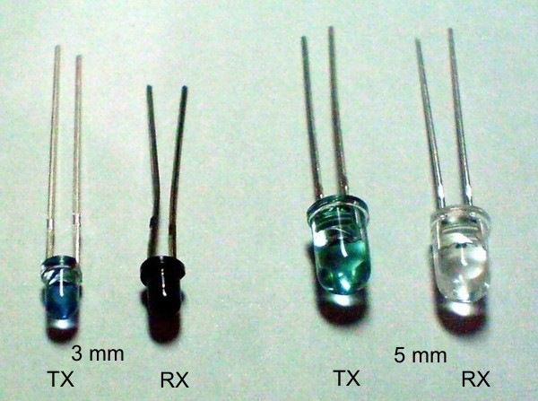
IR
LED is one of the used source of infrared rays. It comes in two packages 3mm or
5mm. 3mm is better as it requires less space. IR sensor is nothing but a diode
that is sensitive for infrared radiation. The infrared transmitter and infrared
receiver are called as IR TX-RX pair. This IR TX-RX pair can be obtained from
any decent electronics component shop and costs less than 10Rs.
Color of IR transmitter
and receiver is different. However, you may come across the IR TX-RX pairs
which appears exactly same or even has opposite colors than shown in the above
picture and it is not possible to distinguish between TX and RX visually. In
case you will have to take the help of multi-meter to distinguish between them.

Here is how you can distinguish between
IR TX-RX using Digital Multimeter(DMM):
Ø Connect cathode
of LED to positive terminal of DMM
Ø Connect anode
of the same LED to a common terminal of DMM
Ø (it means to
connect the LED such that It gets reverse biased by DMM )
Ø Set multimeter
to measure resistance up to 2M Ohm.
Ø Check the
reading.
Ø Repeat the
above procedure with the second LED.
In this process, when
you get the reading of a few hundred Kilo Ohms on digital multimeter, then it
indicated that LED that you are testing is an IR sensor. In case of IR
transmitter, digital multimeter will not show any reading.


Testing
of IR sensor
The following snap shows typical multimeter reading obtained when IR receiver is connected to it as mentioned above. The second snap shows how the sensor’s resistance increases when it is covered by a finger. These are just illustrative figures and readings will depend upon sensor as well as DMM that you are using.
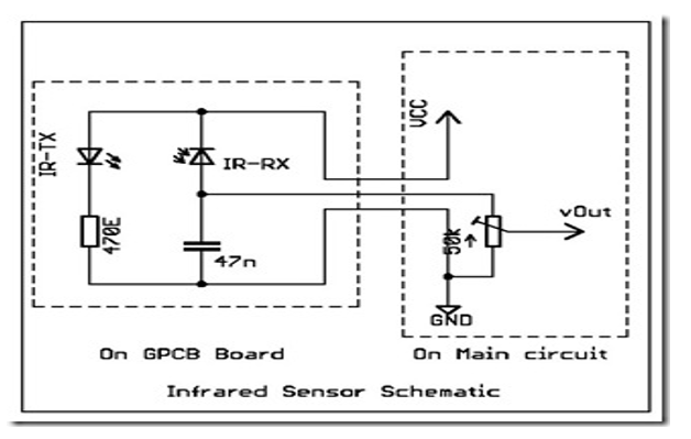
The circuit diagram: Circuit diagram for the IR sensor
module is very simple and straight forward.

Schematic
diagram of IR sensor
IR TRANSMITTER:

Transmitting section of IR sensor
IR LED:
IR LED emits infrared radiation illuminates the surface in front of the LED. Surface reflects the infrared light. Depending on the reflectivity of the surface, amount of light reflected varies. This reflected light will made incident on reverse-biased IR sensor. When photons are incident on the reverse-biased junction of this diode, electron-hole pairs are generated, which results in reverse leakage current. The generation of electron-hole pairs depends on the intensity of incident IR radiation. Reverse leakage current can be caused by intense radiation. This leakage current can be passed through a resistor so as to get a proportional voltage. Thus as intensity of incident rays changes voltage across resistor will varies accordingly.
This proportional voltage can then be
given to OPAMP based comparator. Output of the comparator can be read by
microcontroller. Alternatively, to perform a comparison in software and to
measure this voltage you can use on-chip ADC in AVR microcontroller.
General
diagram of IR sensor
PRINCIPLE
OF OPERATION:
A
photodiode is a type of photodetector that is capable of converting light into
current or voltage depending upon the mode of operation. General Semiconductor
diodes are similar to Photodiodes, that they can either exposed to detect
vacuum UV or X-rays or packaged with a window or optical fiber connection to
allow light to reach the delicate part of the device. Many diodes designed for
to use as a photodiode which will also use a PIN junction rather than the
typical PN junction.
VIBRATION SENSOR
Vibration sensor is used for vibration monitoring and analysis and it is a machine mounted sensor. The three main parameters representing motion detected by vibration monitors are displacement, velocity, and acceleration. These three parameters are mathematically related and can be derived from a variety of motion sensors. The selection of sensor is proportional to displacement, velocity or acceleration and it depends on the frequencies of interest and the signal levels involved. Vibration sensors are not installed directly on the things.
Accelerometer
Accelerometer is one of the most common type of vibration sensor. Accelerometers come in a variety of designs, and they can detect a wide range of different vibrations. Piezoelectric sensor is one of the most popular versions of the accelerometer sensor. This type of sensor contains a material such as crystal quartz which gives off an electric charge when it detects changes in pressure. Piezoelectric accelerometers measure the amount of electric charge that gives off, then it becomes possible to determine the amount of vibration going on in the connection.
VELOCITY SENSORS
Mainly velocity sensor are used to measure motion and balancing operations on rotating machinery. Velocity sensors are ideal for sensing low and mid-frequency vibrations, but not high-frequency ones. For velocity sensor no electrical input is required in order to measure the force of velocity. These velocity sensors do require regular maintenance to be sure that they're operating properly, however this regular maintenance is especially required for the sensors who are placed on machinery which moves at a very high velocity since the sensors need to be firmly anchored to get accurate measurements.
PROXIMITY SENSOR
A proximity sensor is a type of vibration sensor that's meant to measure the distance between an object and the probe. If the object is vibrating that means it will be moving towards and away from the probe, and by picking up on that motion the sensors can detect the range of vibration taking place. The small applications like detecting vibrations with machinery, or for large applications like detecting vibrations in the earth as a sign of earthquakes can be done by using these probes.
ULTRASONIC SENSOR
Ultrasonic sensors is used to measure the distance of an object, they are also known as transceivers when they both send and receive. Ultrasonic sensors work on the principle of emitting sounds waves at a high frequency which is similar to radar or sonar, which evaluates attributes of a target by interpreting the echoes from radio or sound waves respectively. Ultrasonic sensors generate high-frequency sound waves that are too high for humans to hear, and it evaluates the echo which is received back by the sensor. The ultrasonic sensor calculates the time interval between sending the signal and receiving the echo to determine the distance to an object.
This ultrasonic technology is used for measuring wind speed and direction (anemometer), the fullness of a tank and speed through air or water. To measure speed or direction, ultrasonic device uses multiple detectors and calculates the speed from the relative distances to particulates in the air or water. If an ultrasonic sensor needs to measure the amount of liquid in a tank, the sensor measures the distance to the surface of the fluid. Further applications of Ultrasonic sensors includes humidifiers, sonar, medical ultrasonography, burglar alarms and non-destructive testing.
In most cases, the Ultrasonic sensor uses a transducer that generates sound waves in the ultrasonic range which is non-hearable to humans, above 18,000 hertz, by turning electrical energy into sound, After receiving the echo then it turns the sound waves into electrical energy which can be measured and displayed.
· VCC ->
Arduino +5V pin
· GND ->
Arduino GND pin
· Trig ->
Arduino Digital Pin 2
· Echo ->
Arduino Digital Pin 2

Ultrasonic sensor
Features:
§ Detecting
range: 3cm-4m
§ Best
in 30 degree angle
§ Electronic
brick compatible interface
§ 5VDC
power supply
§ Breadboard
friendly
§ Dual
transducer
§ Arduino
library ready
Specifications:
Supply voltage
|
5V
|
Global
Current Consumption
|
15
mA
|
Ultrasonic
Frequency
|
40k
Hz
|
Maximal
Range
|
400
cm
|
Minimal
Range
|
3
cm
|
Resolution
|
1
cm
|
Trigger
Pulse Width
|
10
μs
|
Outline
Dimension
|
43x20x15
mm
|
Specifications
of ultrasonic sensor
Hardware Installation

Signal
representation of ultrasonic sensor
Short ultrasonic pulses can transmitted at the time 0, reflected by an object. First, the ultrasonic senor receives this signal and converts it to an electric signal. When the echo is faded away then the next pulse will be transmitted.This time period is called cycle period. The recommend cycle period should not be lesser than 50ms. If a trigger pulse with a width of 10microsecond is sent to the signal pin, then the Ultrasonic module will output eight 40kHz ultrasonic signals and detect the echo back. The echo pulse width is proportional to measured distance and can be calculated by the formula above. If no obstacle is detected, then the output pin will give a 38ms high-level signal.


No comments